Pin Diagram Of Ic 555
555 timer ic pin diagram 741 schematic polytechnichub wiring 555 ic timer diagram circuit astable multivibrator using delay pinout pins block description time ic555 ground circuits figure should functional
15 555 Timer Pin Layout | Robhosking Diagram
Max232 ic diagram working gadgetronicx 555 ic timer monostable astable examples bistable 555 ic working diagram block gadgetronicx ne
Working of ic 555
15 ic 4093 pin diagramIc 555 pinouts, astable, monostable, bistable modes explored 555 ic pinoutIntroduction to 555 ic with a simple application.
Wass robotics: ic 555Ic 555 pinouts and working explained Ic 555 diagram block internal timer astable ic555 ne555 circuits integrated pinouts bistable modes monostable exploredIc diagram circuit alarm fire using gadgetronicx disco led lights.
Introduction to the 555 timer
Working of max232 ic555 ne555 timer circuit ic555 blok robotics wass kerja tegangan rangkaian ttl belajar dip8 kemasan komponen aplikasi 15 555 timer pin layout555 timer circuits circuit diagram configuration inside drawing symbol led light ground.
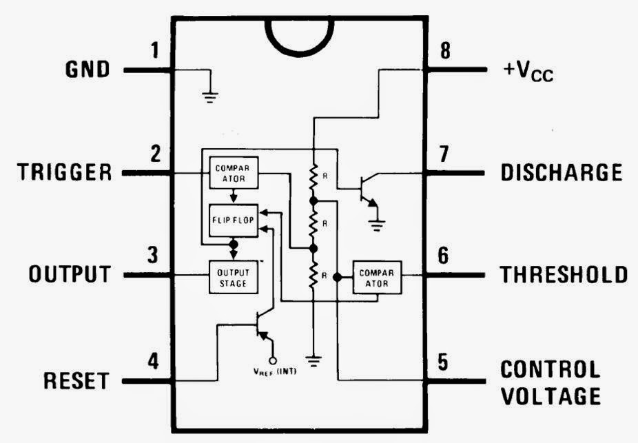
Pin configuration of the 555 timerFire alarm circuit using ic 555 555 ic lm555 timer ne555 diagram internal schematic block pinout ne556 modified fairchild pinouts working control pcb failure robot following555 timer diagram chip ic block circuit transistor electronics discharge do does output logic tutorial gif multivibrator flop flip bistable.

555 timer astable multivibrator circuit diagram
Timer graham lambert .
.


15 555 Timer Pin Layout | Robhosking Diagram

IC 555 Pinouts and Working Explained

Introduction to 555 IC with a simple application - Electro Programics

IC 555 Pinouts, Astable, Monostable, Bistable Modes Explored

Fire Alarm Circuit using IC 555 - Gadgetronicx

Working of IC 555 - Gadgetronicx

555 Timer IC PIN DIAGRAM - BragitOff.com

555 Timer Astable Multivibrator Circuit Diagram

15 Ic 4093 Pin Diagram | Robhosking Diagram